Home automation for only $22.13! Sounds too good to be true, and actually you will need something more: 433 MHz power switches (Dutch: klikaanklikuit modules) to use the wireless opportunities. But without, you still can use 8 relays with your cellphone or any device with internet.
A few months ago, a friend came to me for some help with his home-automation wish: control everything in his apartment with only one remote. So we started this project.
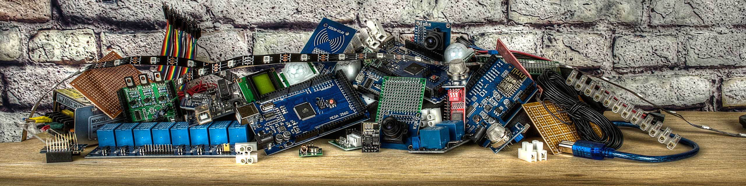
The list of needed parts:
| 1 Arduino Mega clone |
$ 7.10 |
| 1 ESP 8266 WIFI module |
$ 1.24 |
| 1 set RX / TX 433 mhz. |
$ 0.37 |
| 1 block with 8 relays |
$ 3.88 |
| 1 power-unit |
$ 4.41 |
| 1 OLED screen |
$ 3.23 |
| 1 push button |
$ 0.71 |
| 1 small piece of PCB |
$ 0.18 |
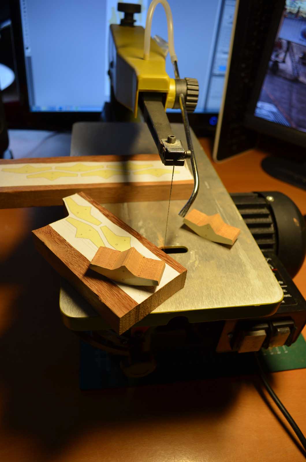
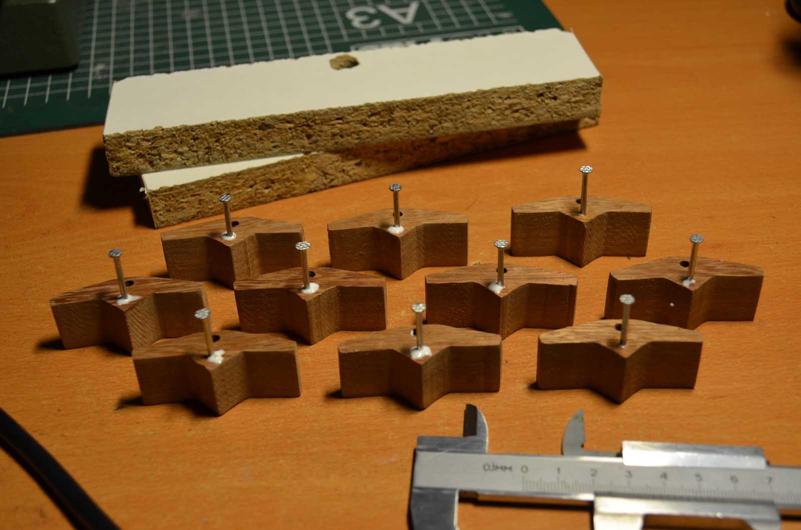
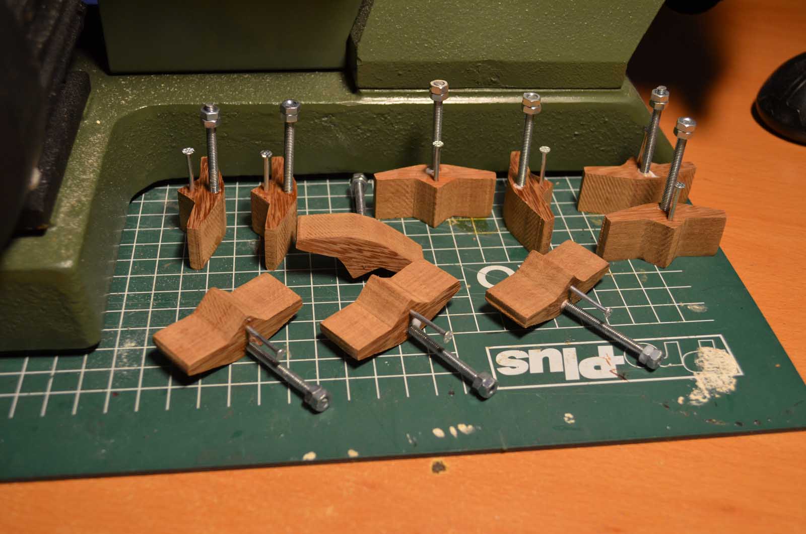
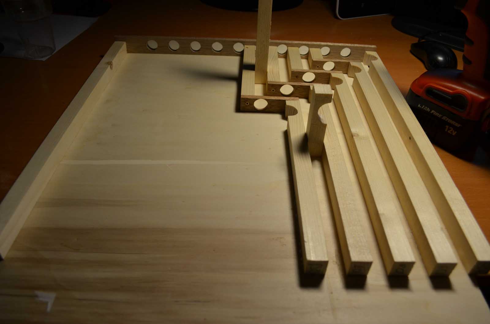
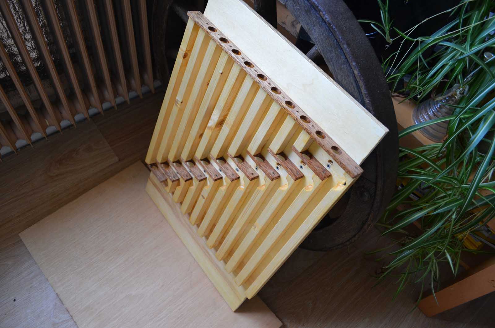
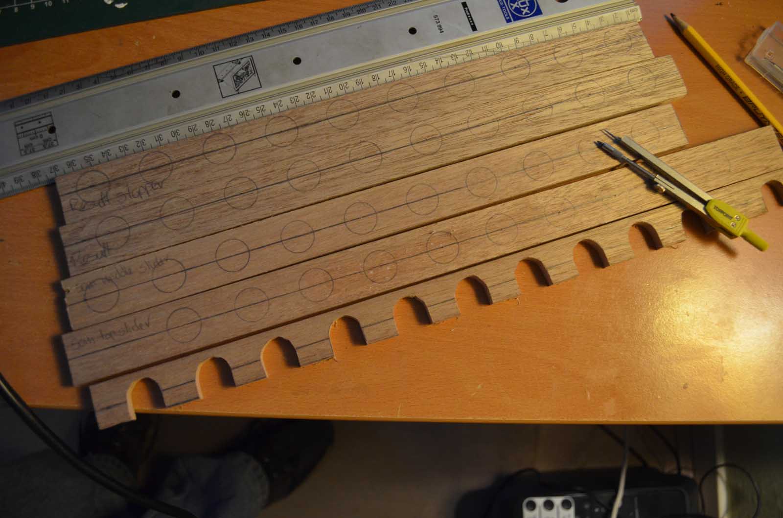
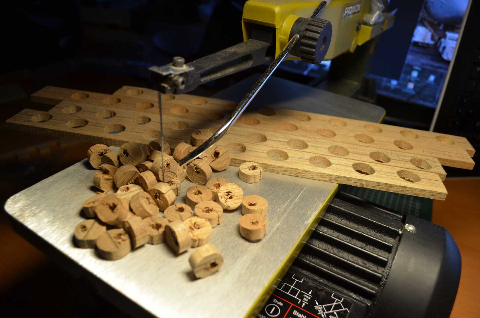
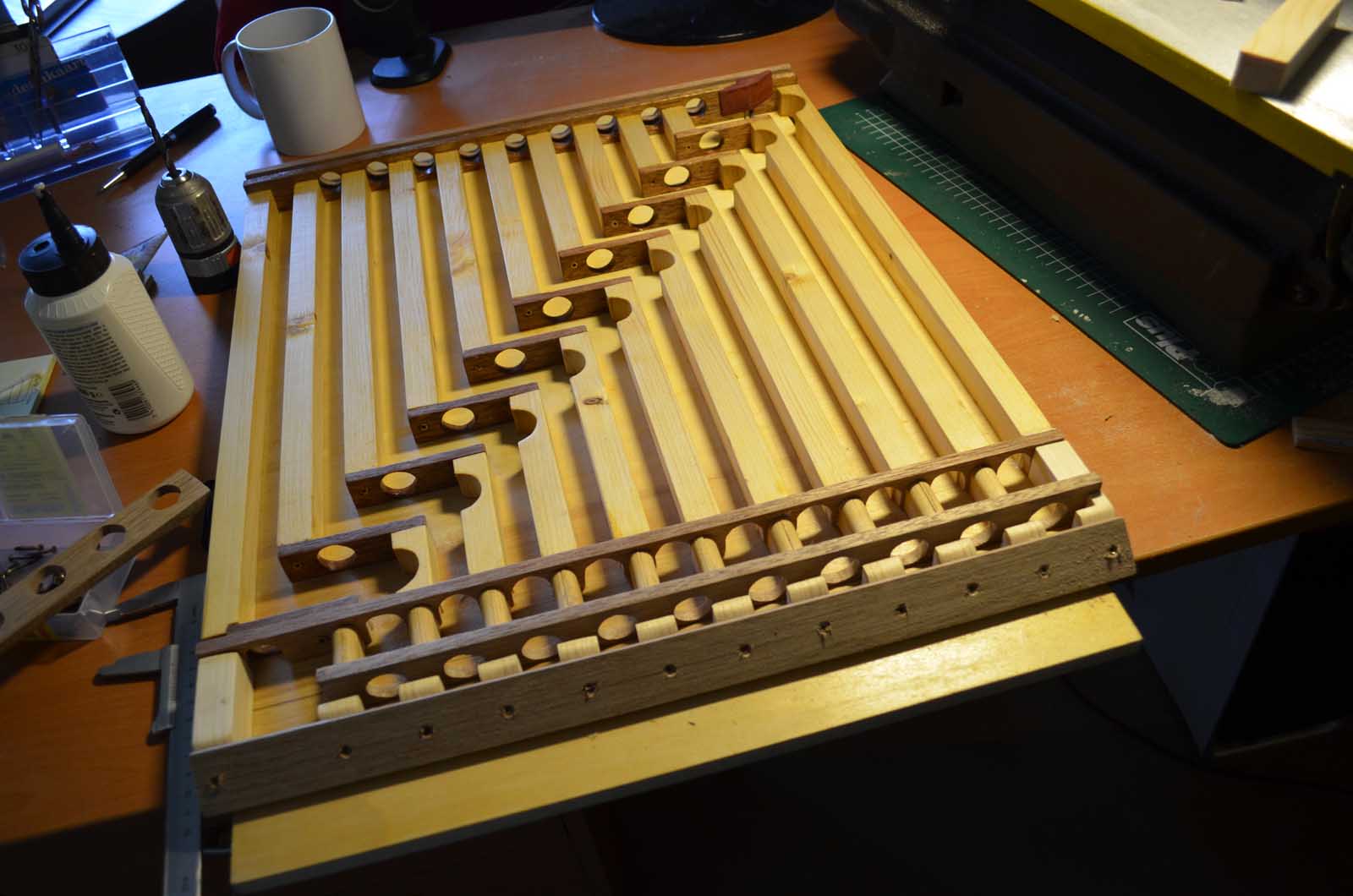
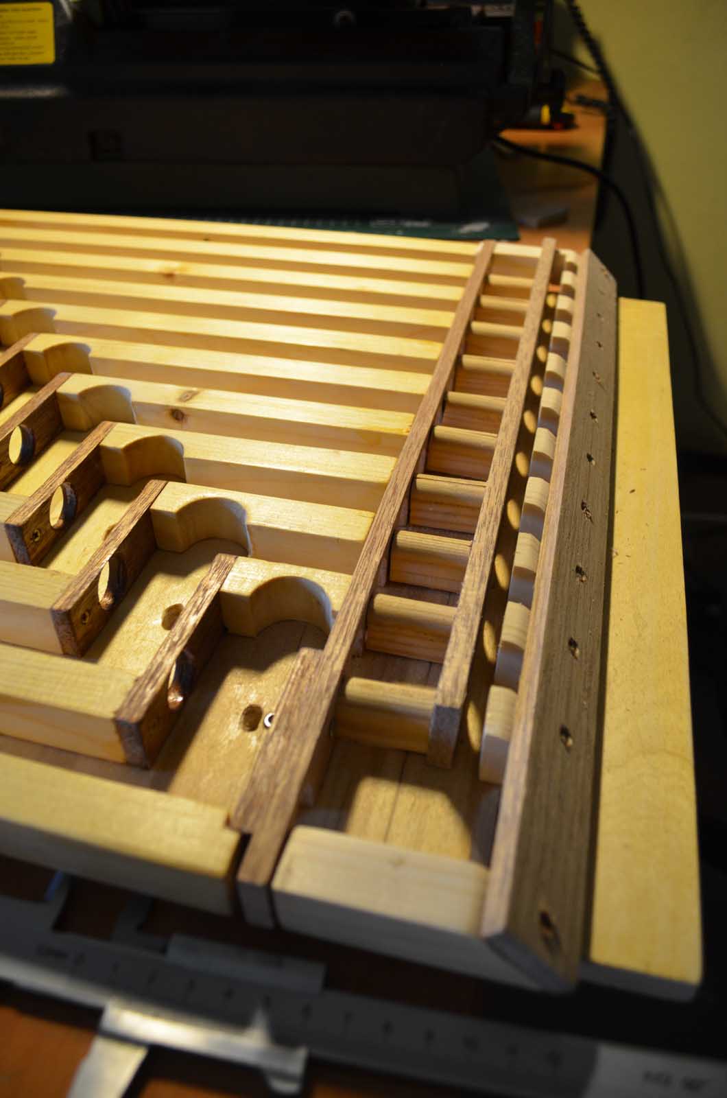
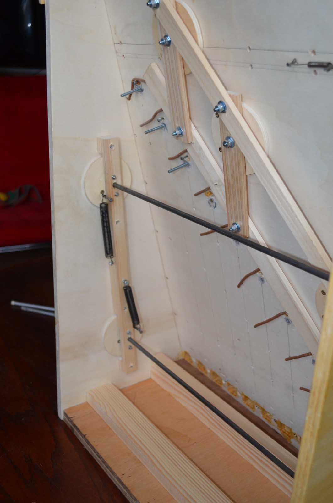
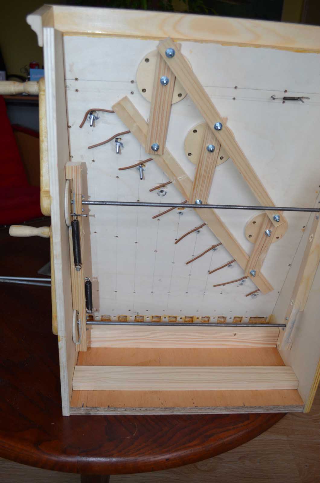
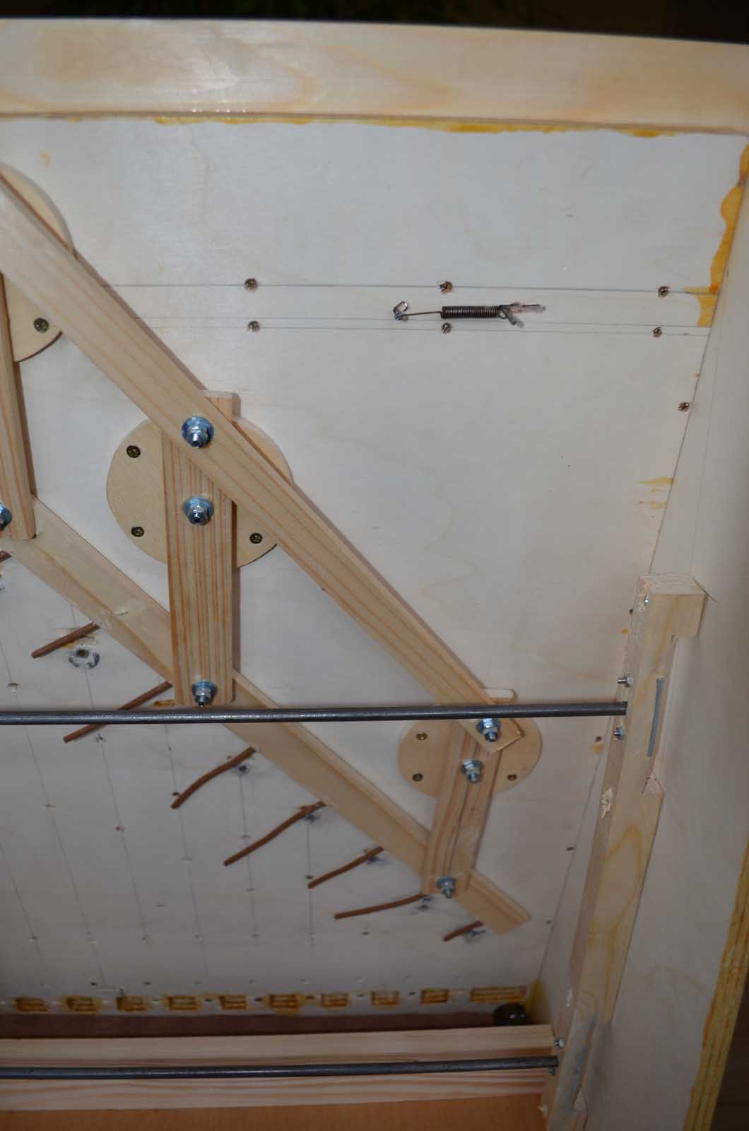
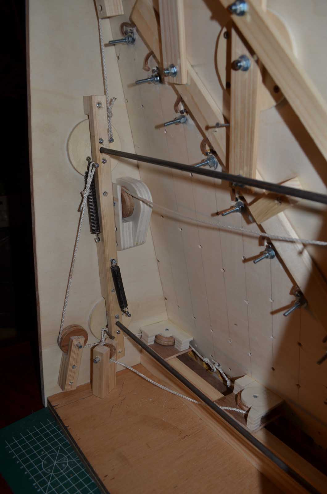
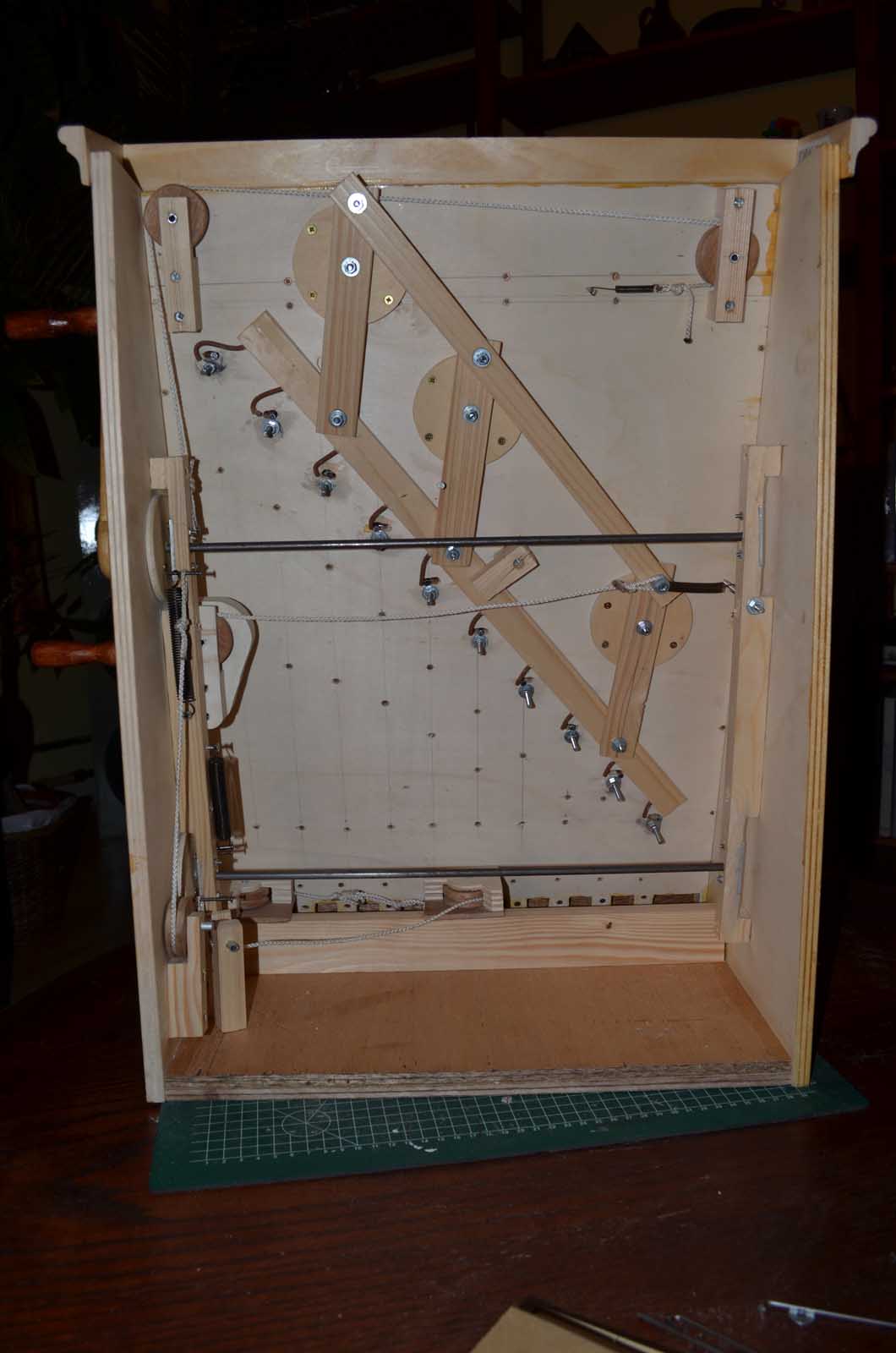
And, of course some scrap wood and other materials. I used plexiglass for my casing. I like to see the connected parts, but at the lower level it's no weak current: depending on your country, the relays will switch 110-230 volts. So the entire package I made will be stored in a wooden box once its operational.
What can it do?
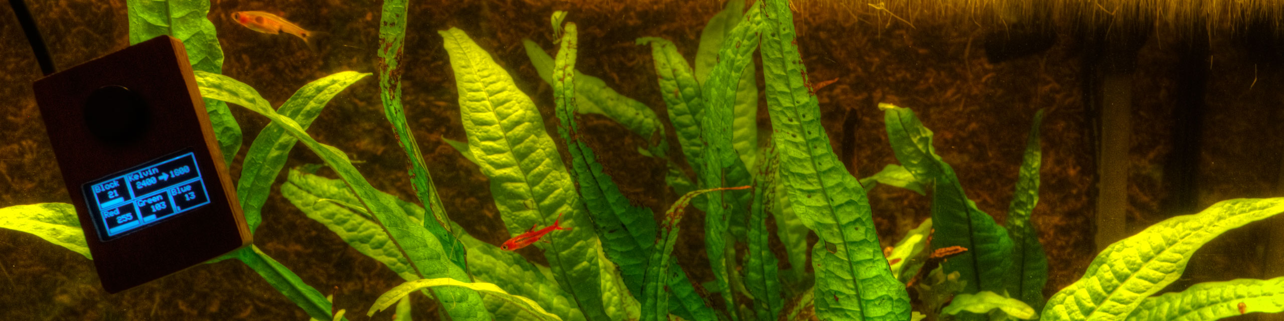
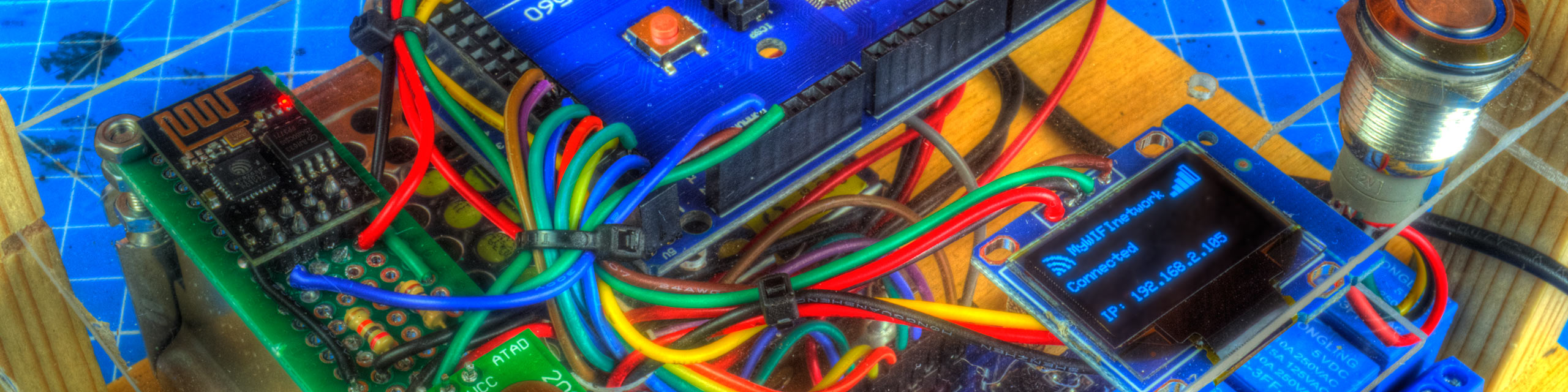
After the unit is powered, it will connect to a WIFI network. The OLED screen looks pretty small, but can be read very easily. Once connected, it shows the IP address where you can find it's control center. It's a local address, so only available when you are connected to the same network. Of course it's possible to configure your access point to make it visible from outside your network, but the whole world gets the ability to switch off your coffee machine. So be warned...
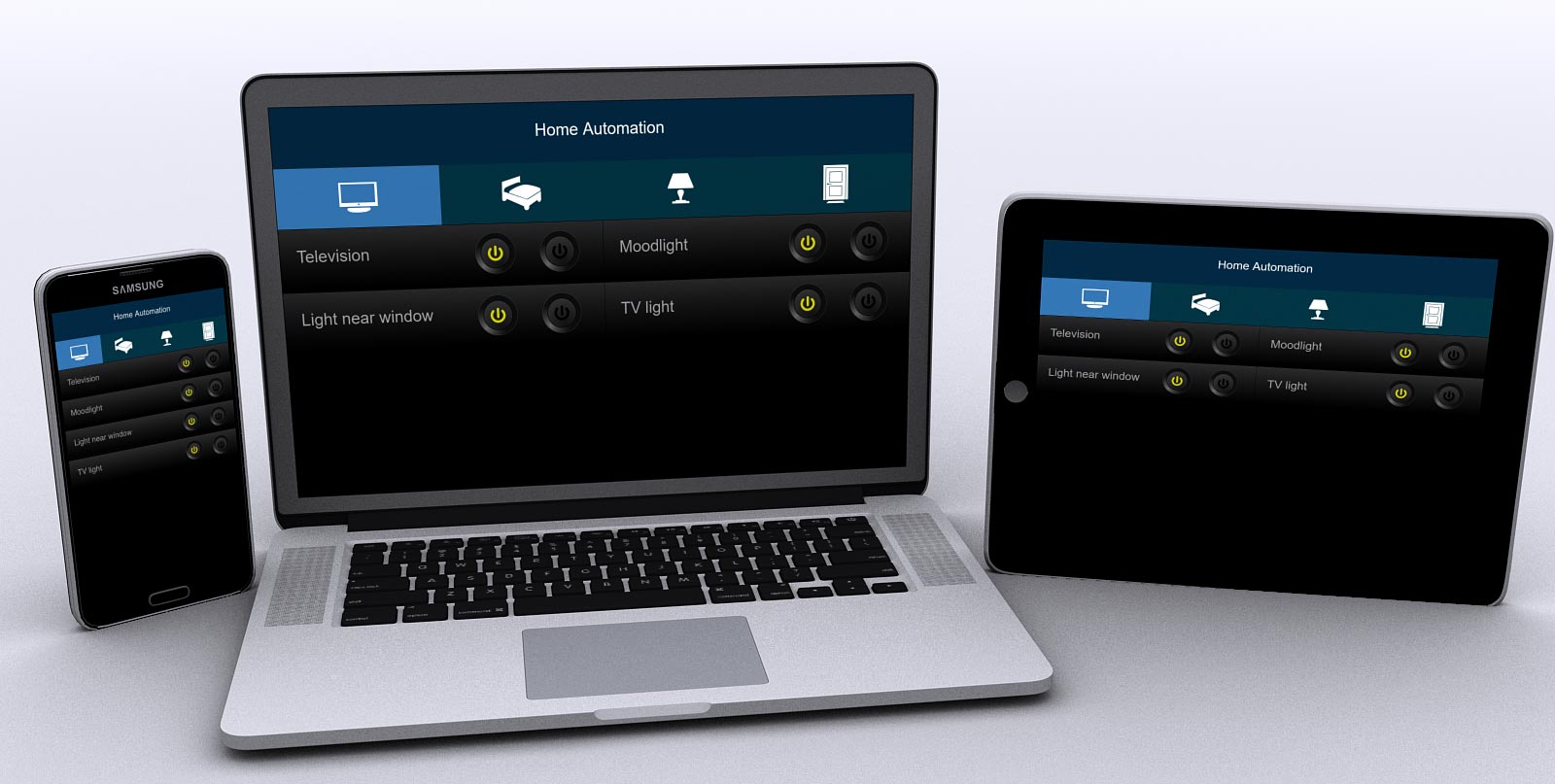
Once your cellphone, tablet or laptop has loaded the website, it can control everything connected to the relays and the radio transmitter. The website uses AJAX for sending the commands, so there is no delay for reloading the website every time you turn a switch.
Choices and decisions
|
The Arduino Mega and the Wemos D1 mini
|
We started this project first with a Wemos D1 mini. It has some major advantaged above the Arduino Mega:
- It's very small
- It's very cheap (below $3.00)
- It has lots of memory to store vars.
- There is no need for an external WIFI-unit: it is embedded on the circuit board.
- Using WIFI is very easy, as this kind of board is a real IOT board.
We discovered also some disadvantages:
- It has only a few pins (9) for input/output, and some are still in use by the Serial line or the WIFI.
- Because we needed all pins, the Serial monitor could not be used for tracing purposes. Programming and debugging became a little slow due to the lack of this kind of monitoring.
Some problems can be solved by using an extension board. You offer one or two pins, to get four till eight in return. We decided to switch to an Arduino Mega clone because of the next advantages:
- More sets of RX / TX serial ports. That makes it easy to remain connected to your Arduino IDE (and serial monitor) while using another serial port for the WIFI simultaneously.
- Lots of input/output pins.
Beside the advantages, there are also some disadvantages. The main problem is the small amount of memory (8 kb for storing vars) and the combination with the ESP8266 WIFI unit. The connection between them needs to be read as text (char or strings), and you even have to store/collect messages to interpret them once they're completed. And last but not least: the website itself needs to be stored on the Arduino also. More text to store.
AT+RST

OK
WIFI DISCONNECT

 ets Jan  8 2013,rst cause:2, boot mode:(3,7)

load 0x40100000, len 1856, room 16
tail 0
chksum 0x63
load 0x3ffe8000, len 776, room 8
tail 0
chksum 0x02
load 0x3ffe8310, len 552, room 8
tail 0
chksum 0x79
csum 0x79

2nd boot version : 1.5
  SPI Speed      : 40MHz
  SPI Mode       : DIO
  SPI Flash Size & Map: 8Mbit(512KB+512KB)
jump to run user1 @ 1000


Ai-Thinker Technology Co. Ltd.

ready
Above the response after a given AT+RST command (a reset)
The storage of text (Strings) is complicated on an Arduino. It's the only var with unknown memory usage when it's declared. Besides that, you clone (and double the usage of memory) very often when working with strings: pass it through a function, edit it, etc.
Once your memory is filled up, your Arduino will behave strange: resets without warning, program crashes, unexpected return-values from functions, and almost every time no signals from the serial ports anymore...
Connecting the modules
For this project there will be 5 modules connected to the Arduino. Most of the pin assignments are not critical. In other words: most of the destination pins can be changed, but a modification of the program will be necessary. In my case, I've decided to choose the pins on the short side of the PCB, to make shorter connections and to prevent the wires to mess up.
The ESP8266
This module is used to connect your Arduino to the internet, or in this case: to your local network. As mentioned above, it communicates with two serial lines (RX and TX). This is the only module needing 3.3 Volt, instead of 5.(!) That means that not only the VCC should be treated in a different way (do not connect it to your 5V power supply, connect it to the 3.3V pin of your Arduino), but also you need some resistors on the RX line to lower the voltage.
It's also mentionable that this WIFI module only uses the 2.4 GHz band and is not able to connect to the modern 5.0 GHz band. As far as I can see that won't be a problem right now, as I don't know one single router with only the 5 GHz band.
In this project we use pin 18 and 19 to connect to the Arduino. Those are not critical, as an Arduino has four sets of serial ports:
The communication pins on the Mega |
RX 0 and TX 0 have been set aside, as they will be used for program uploading and the serial connection (with the monitor, plotter and IDE) on your computer.
The other ones are not in use. I do not know if they are exactly interchangeable, but I've chosen RX1 and TX1. If you want to change to another set of lines, change the program, and replace all "Serial1." commands to "Serial2." (or "Serial3." of course).
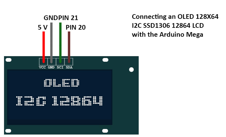
The OLED I2C SSD1306 12864 LCD
The first time I received one of these OLED modules, I got surprised by the fact that its size is no problem at all! As they are really small (below 1 inch), you would expect the need of glasses to read them. But actually four lines of text is no problem at all.
The old modules (without I2C) used lots of wires (4 or 8 data lines), but the I2C versions are easy. GND, VCC and a SCI and SDA are needed.
Is the pin configuration critical? An Arduino Mega has one set of SCI and SDA pins. These function like a bus -the I2C bus-. Therefore it is not necessary to change pins when you want to add something more on that bus, devices can share a bus. Communication will be separated by the use of an address. That means that you'll have to check the address of your screen and correct it in the program. (More explanation in the check your module section)
The FS1000a transmitter
Normally you'll buy them as a set, and even you don't need the receiver in your final setup: don't throw it away. You will need it to get the codes from the remote controls of your wireless switches. As you can see, there is a small hole on the FS1000a with the description ANT near it. You can add an antenna to it when the unit cannot reach the desired distance. Tests over here showed no problem over 10 meter, so I did not attach one.
I used pin 53 on the Arduino, but every pin can be used. You only have to change the program on this line:
#include <RCSwitch.h>
RCSwitch mySwitch = RCSwitch();
#define pinTX 53
Change the 53 to another free pin when desired.
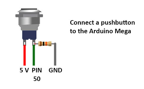
And last but not least: a pushbutton
This is a button which only creates a circuit during the push. It is meant as a wake-up-button for the screen, as I do not want it to display info 24/7. Once the button is pressed, it lights up de display for 60 seconds. As you may know, the button needs to be connected with a pull down resistor.
Another alternative is to use a switch (on / off), and connect it on the 5V line of the OLED, to interrupt the circuit, and the OLED is turned off for real. (Notice that the pushbutton system does not interrupt the power, the program stops using the screen)
Checking the modules
It can be really frustrating when you put everything together in a nice casing, with all wires cut to the desired length, and you discover problems... So I suggest to test all modules separate and together before wiring if permanent. Use a breadboard and some Dupont cables to wire it up, and use the test programs to make sure everything works fine.
Checking the ESP8266
After wiring it up, use the next program when connected to your computer. Your serial monitor should tell you the results of an attempt to connect to your WIFI network.
void setup() {
  Serial.begin(9600);     //<--This is the connection with your computer.
  Serial1.begin(115200);  //<--This is the connection speed with your ESP.

  // WiFi SSID and Password
  String SSIDstring = ("#####");            //Replace ##### with your network name / SSID
  String PASSstring = ("#############");    //Replace ########### with the password of your network

  useESP("AT+RST\r\n", 2000);
  useESP("AT+CWMODE=1\r\n", 2000);
  useESP("AT+CWLAP\r\n", 8000);
  useESP("AT+CWJAP=\"" + SSIDstring + "\",\"" + PASSstring +"\"", 6000);
  useESP("AT+CIPSTATUS\r\n", 2000);
  useESP("AT+CIPMUX=1\r\n", 1000);
  useESP("AT+CIPSERVER=1,80\r\n", 1000);
  useESP("AT+CIFSR\r\n", 1000);
}

void loop() {
}

String useESP(String command, const int timeout) {
  String response = "";
  Serial.println("==================================================");
  Serial.println("The Arduino sends the next command to the ESP8266:");
  Serial.println(command);

  Serial1.print(command);   //<-- This is the real command to send to the ESP

  Serial.println("..................................................");
  Serial.println("Waiting for response...");
  long int time = millis();
  while( (time + timeout) > millis()) {
    while(Serial1.available()) {
      char c = Serial1.read();
      response += c;
    }
  }
  Serial.print(response);
  return response;
}
The program communicates using serial 1 (TX1 and RX1) with the ESP8266. The program will show you the given command, and the response of the ESP8266.
Under normal circumstances, you should see the reset (RST) command, after which the ESP generates a summary. You also see a list of networks in your area, and the program tries to connect to your network. If that is possible, it will show you the given IP address. (a reference of usable commands can be found here)
When it does not connect, you still will get output on your monitor. (Otherwise your Arduino cannot communicate with your computer). If there is no response from your ESP8266 at all:
- No response at all can also be a result from a wrong baud-rate of your serial connection with the computer. (duh....) Both on 9600?
- Try a different power supply. On the web you can find problems with unstable power. You can also test with a power bank (has a USB connector itself!), a cellphone charger (idem) or even battery packs. (When you feed the Arduino 5 V through USB of a 5V line, it generates 3.3 for the ESP itself)
- An unstable kind of power can be solved with the use of a capacitor between 3.3V and ground. When there is a (little) noise on the power lines, most modules will work, but not the ESP8266. Even when its power led is on.
When there is response, but totally unreadable, too short or the word "busy..":
- Try another bitrate (baud) for the communication on Serial1 (= with the ESP). Maybe your version of firmware has a different baud rate.
- Shut down the power for some time. Every time you reset your Arduino / upload a new program, the ESP does not reset by itself. (it remains powered) In some cases, it is waiting for something (like a close command or a website to send of a given number of characters) and shall not take new orders before the current task has been finished.
Testing the FS1000a
To test the FS1000a, we need 3 more things:
- Some device or switch which uses the 433 MHz protocol for input. A big part of our project are the wireless switches, and our project is going to replace it's remote controls.
- We need the remote controls itself, to learn the code to be broadcasted.
- Therefor, we also need the 433 MHz receiver, but as we bought the RX and TX as a set...
Attach the receiver to 5V and ground, and connect one of the middle two data-pins to Arduino pin 2. You will nead an extra library if for your Arduino, so make sure RC-Switch is installed (of not, get it!).
The library of RC-Switch can handle the protocol we need. But not all power outlet sockets use the same protocol. It will be possible that you need another library of other hardware for your wireless switches, but the "klikaanklikuit" devices over here work.
Once you've setup the breadboard. just start the "ReceiveDemo_Advanced" script on your IDE. (Examples > RC-Switch > ReceiveDemo_Advanced)
Now you can use one of your remotes (maybe disable the receivers before...) and take a look at the information on your serial monitor:
Decimal: 3700159 (24Bit) Binary: 001110000111010110111111 Tri-State: not applicable PulseLength: 306 microseconds Protocol: 1
Raw data: 9536,268,900,280,912,840,320,864,308,868,304,280,896,292,884,284,880,308,872,884,288,876,300,864,332,268,900,848,320,272,908,848,336,840,324,860,312,276,908,264,908,852,328,844,100,16,92,444,512,
Maybe I take some risk by showing you one of my codes, because everyone with an Arduino / FS1000a combination can broadcast a "3700159" code of 306 microseconds in front of my house to activate the SoundBlaster radio...
Learn all codes from your remote(s). As you can see the pair of codes (on and off for one device) are almost identical, only the "off"-code is one lower. (In my case: you can turn the SoundBlaster off with 3700158)
Now we take our breadboard again, and setup for the transmitter: de FS1000a. Wired as mentioned in the section before, you can run the next test:
#include <RCSwitch.h>

RCSwitch mySwitch = RCSwitch();
#define pinTX         53
#define pulseLength   306
#define bitLength     24
#define protocol      1

void setup() {
  mySwitch.enableTransmit(pinTX);
  mySwitch.setPulseLength(pulseLength);
  mySwitch.setProtocol(protocol);
}

void loop() {
  mySwitch.send(3700159, bitLength);
  delay(2000);
  mySwitch.send(3700158, bitLength);
  delay(2000);
}
With this script, the power outlet socket will be turned on and off every four seconds.
Troubleshooting:
- If you can receive the codes (with the RC-Switch library and the receiver) you would be able to send codes. If you can't receive, there is a possibility of the use of a protocol which cannot be handled by RC-Switch or this hardware.
- If you can receive codes, but sending them won't let anything happen and codes seem to change often... You may deal with a system with "rolling code". As a measure of security, some devices use a system with encryption / calculated keys. As long as you cannot get your hands on their algorithm, it won't be possible to control that kind of devices.
- When their seems to be an unpredictability in your results, there may be interfering factors or a too big distance. Remember, it is possible to add an antenna on the transmitter!
Testing the OLED I2C SSD1306 12864 LCD
The OLED is connected to two special pins: the I2C-bus. As in computers more devices can share one bus, because communication will use addresses. So you need to find the address of your screen first. That can be done with an I2C Scanner. Once you've got it, you can test your screen with the Adafruit SSD1306 library example. (Make sure you also install the Adafruit GFX library) If you'll get the warning to fix your SSD1306 library, open up the Adafruit_SSD1306.h file in your editor. The only line uncommented should be the line with your screen resolution:
/*=========================================================================
 SSD1306 Displays
 -----------------------------------------------------------------------
 The driver is used in multiple displays (128x64, 128x32, etc.).
 Select the appropriate display below to create an appropriately
 sized framebuffer, etc.
  SSD1306_128_64 128x64 pixel display
  SSD1306_128_32 128x32 pixel display
  SSD1306_96_16
-----------------------------------------------------------------------*/
   #define SSD1306_128_64             //<<-- My resolution, this line is oncommented
// #define SSD1306_128_32             //<<-- Not my resolution, this line is commented
// #define SSD1306_96_16              //<<-- Not my resolution, this line is commented
(Normally, this file can be found on your hard drive: users\#username#\documents\Arduino\libraries\Adafruit_SSD1306\ )
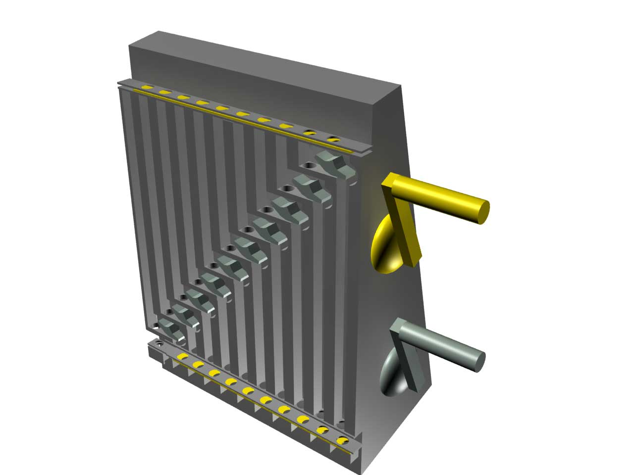
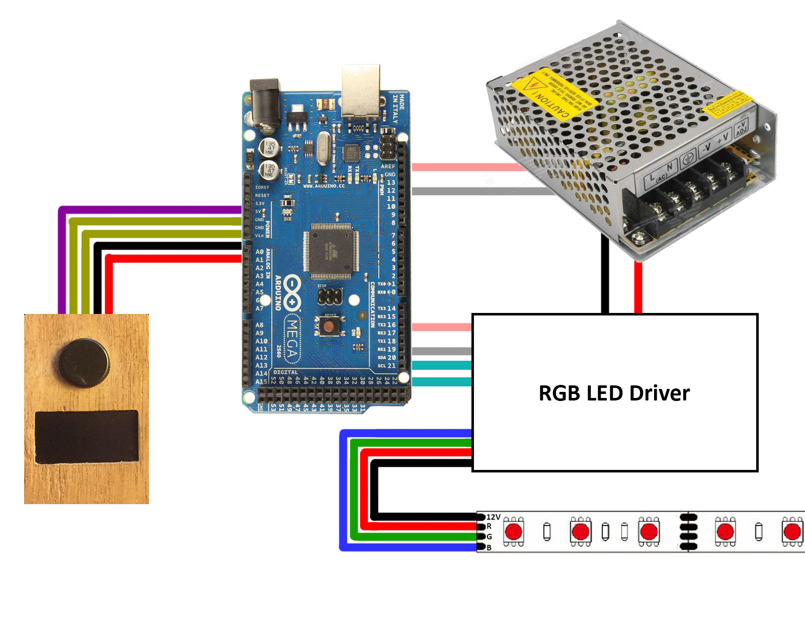
Testing the relay-bank
As you wired as mentioned before, you can use the program below to test your relays. When using for testing purposes, we do not attach the relays to outlet sockets. The relays have LED's on board, so testing is possible without the dangerous alternating current from your wall socket.
void setup() {
  for (int i = 22; i < 36; i = i + 2){
    pinMode (i, OUTPUT);
    digitalWrite (i, HIGH);
  }
void loop() {
  for (int i = 22; i < 36; i = i + 2){
    digitalWrite (i), LOW);       //<-- Turn relay ON
    delay(1000);
  }

  for (int i = 22; i < 36; i = i + 2){
    digitalWrite (i), HIGH);      //<-- Turn relay OFF
    delay(1000);
  }
}
Running these code let all relays go on and off.
Troubleshooting:
- This is the only part with both alternating current and weak current(!), and the PCB has a jumper for more safety: it is possible to operate the relays with another power supply to isolate the Arduino more. In this example we leave the jumper on JD-VCC. So make sure your jumper is at the same position.
Testing the push button
Although there is nothing spectacular about testing a pushbutton, I will test it. When having troubles with the main program, there is nothing more frustrating than "things you would expect to work, but they didn't". So use the button example in the IDE (examples > 2.0 Digital > Button) to check your connections.
The main script
The main script can be used after some adjustments. The next data will be different for everybody:
- The name and password of your WIFI network.
- The (amount of) devices you want to control.
- The grouping of the devices (on four tabs).
- The way you want to control them (with relay of wireless).
- The available radio codes to turn things on and off.
Besides those points, when you can work with HTML it is also possible to change the website, add or remove tabs, change the tab-icons or the turn on and off buttons. On the next page of this article you will find information about the website, as most is hidden in a JS file.
The devices
Make a list with all devices you want to control, and sort them as you want to see them on the website (first device is first item on first tab, second device is second item on first tab, and so on).
- Enter the amount of devices in the program. (const int devices)
- Add the names (in the order meant above) between quotes and seperated by comma's to the const String deviceNames[].
- For every device, add the tab number to const int deviceTabs[]
- Add the destination. What needs to be used when the button of that device is pressed? Destination 1 - 8 are relays, 11 and higher are wireless codes to be broadcasted. (const int destinations[])
For all wireless devices, two codes are needed. One to turn off, and one to turn on. If you use devices which use only a single code like a pushbutton (door openers for example), add the code twice: once on the list of codes to turn on, and once on the list of codes to turn off.
The setup part of the RC Switch contains the pulseLength, which maybe can be different from mine. The pulselength of your wireless switches can be found with the test-program "ReceiveDemo_Advanced" mentioned on the page before.
The OLED screen is bus connected, and will only be able to work when the correct address had been entered in the program:
display.begin(SSD1306_SWITCHCAPVCC, 0x3C); //<-- The address(0x0C) can be different on other OLED screens.
Besides that, run the test-program at least once. It will also warn you when your library "Adafruit_SSD1306.h" needs an adjustment for your resolution. See the module-checking page..
 Download the Home Automation script
The script serves a website, which has dependencies to three other files:
- https://2muchtime.org/projects/ha/ha.css
This is the CSS file for the entire website.
- https://ajax/googleapis.com/ajax/libs/jquery/3.2.1/jquery.min.js
This loads jQuery, which is used in the next file. It doesn’t need to be stores on an own server, as it is allowed to link directly to the Google Apis.
- https://2muchtime.org/projects/ha/ha.js
The JavaScript file does the big part: This file not only contains the functionality, it is also necessary for building up the HTML and building up the images (all SVG)
I can imagine you need to change ha.js, as it contains the images. And most people won’t use the same TV, light, bed and door icon I do. So you need to have access to a web server to store ha.css and ha.js. On the next page, you can find the zip files of these two files.
For testing purposes or “just wanting the same version I have”, you can use the ones stored on the 2muchtime server. (Link to the addresses above, not to their zip-file)
And off course: using your own files means you have to change the script on your Arduino: recplace the URLs in the string of the website with your own locations.
The website
To reduce the risks, the program sends a very small website, about 450-500 characters (depending on the devices):
<!DOCTYPE html>
  <head>
    <link href="https://2muchtime.org/projects/ha/ha.css" rel="stylesheet" />
    <script src="https://ajax/googleapis.com/ajax/libs/jquery/3.2.1/jquery.min.js"></script>
  </head>
  <body>
    <div id="c" style="display:hidden">
      2muchtime Domotica,*,Television,Moodlight,Light near window,TV light,*,Moodlight bed,Bedside table light,*,Desk light,Light at backside,
      General,Light above table,*,Front door
    </div>
  </body>
  <script src="https://2muchtime.org/projects/ha/ha.js"></script>
</html>
Above the website as will be server by the Arduino to your browser.
The website has dependencies to three files: jQuery, a CSS file and a JavaScript file. All will be served from another server.
The JavaScript file is used for the next purposes:
- It reads the value of the <DIV> tag, and separates that into a title, and all devices. A * is the separation character to go to the next tab. Finally it removes the content of the div.
- It builds up the entire website by adding the title, the tabs and a responsive square for every device with a power-on and power-off button.
- It contains all six images, which are actually SVG images.
- On a window resize, it will act responsive and recalculate the location of buttons.
- It handles the tab-navigation.
- It contains a little AJAX to send information (a button press) to the server without a page reload.
The files can be found here:
Download the Javascript file (zip)
Download the CSS file (zip)